Creating a DirectX12 3D Engine When You Know Nothing About 3D Programming
Who am I and why did I do this?
Before digging more into what this challenge entails, let's recap on what kind of engineer I am, because I feel that it is imperative to understand how hard this challenge is. I have, for the longest time, worked on data engineering. My jobs were heavily geared towards the following: I have a bunch of data flowing everywhere, and I need to store it and query it efficiently in order to build any kind of applications. I have even done a PhD on this topic and cranked up my engineering skills. However, I dipped my toes into low-level optimisations here and there because that's what you need sometimes to improve performance.
Two years ago, I entered the gaming industry by a weird door. Because I was doing independent research on various topics around input latency for games, I was hired at Ubisoft to create new applications with game streaming. I won't talk about it more because that's not the point here, but let's just say that I interact with games on a daily basis and I have to make sure that the games don't crash on me when I use their DirectX context, or behave weirdly when I send them inputs. However, at no point in my education or personal projects have I created a game, or even drew a triangle. I basically improvised my way by using my reverse engineering skills and my global understanding of the topic (my input lag research helped a lot).
One day, I saw this video by Sebastian Lague who showed that he was able to think of an idea for a feature for his 3D scene, explain it in a few sentences and implement it (note: he is using Unity). I saw it as a signal to start a new project to be "creative in 3D" whatever that would mean. But, the end goal would still be to better understand how a game works at low-levels, so using a pre-existing engine like Unity, Unreal or even the ones I have at work like Anvil, was out of the question. I needed to understand how it worked, so I had to create it from the ground up.
The end goal
So here is the goal I've set out for myself: create a 3D engine that is able to display a moderately complex scene with decent lighting. Here's a bunch of rules:
- It will be written in DirectX 12
- DX12 is the most complex API of the DirectX line, if you get it, you get the ones below.
- I mostly interact with DirectX at work.
- DX12 is the most complex API of the DirectX line, if you get it, you get the ones below.
- I will not use any external library. Only the APIs provided by the system.
- I'll make some exceptions, but it will not be for the core part.
- I'll make some exceptions, but it will not be for the core part.
- I will make things my way. No copy pasting from tutorials.
The idea is for it to be a playground to have fun. If I want to add fog for instance, I can hop in and add it if I want. Same thing as Sebastian Lague did.
How to even start?
I've tried this challenge a couple of times in the past, but couldn't go past the first couple of tutorials. Because the topic is actually complex, it was either too magical (e.g. "do this and it will work") or too obscure (e.g. sentences where I didn't understand half of the concepts)..
Now that I have done it, I can tell you that it is one of the most challenging projects I have ever attempted. And I have done plenty of weird things in the past. The main issue is that it's a whole new world™, which is COMPLETELY different from CPU-only programs that I have made all my life.
My starting point was this tutorial from Jeremiah at 3D GEP. It was an invaluable resource for me but I am not sure that I would recommend it. The main point is that you need to be senior-level in C++ to not be overwhelmed. But it is the most complete I could find, especially one that explains the core concepts in detail and applications in practice.
My goal for the next chapters is to explain how each part of a 3D engine works. My restriction will be to mainly talk about the concepts and barely show any code. For me, the code and the syntax is not important, if you understand the ideas, you can apply it to your application, even if sometimes it might be challenging to do the translation of concepts. Without further ado, let's jump right in.
The first window: a lot of plumbing
This section will be hard. Because I'm going to set the scene, pun intended, and prepare all the concepts necessary to draw something. There are lots of them and creating an empty window and displaying a solid background needs a dozen or so operations on top of the creation of the window.
However, this is really important as all the neat things like plonking a fancy texture on a model in 3D needs plumbing to be able to send commands to your graphics card at some point. So, strap on and if you feel overwhelmed, take a break and maybe look at the other chapters and come back later when you need to clarify some ideas.
Concepts
Adapters & Devices
Everything starts with something that will be able to do graphics, it is called an Adapter. Its role is to represent a piece of hardware, usually a GPU (graphics processor) and its dedicated memory. Sometimes, for instance when you have a gaming laptop, you may have multiple adapters, your program has to pick the one you want. With an adapter, you can create a Device which will be the main interface for your program to talk to it. Even if you create other objects, they are inherently linked to the device. During the rest of this article, I will use the usual shortcut of using "GPU" to denote the entire adapter.

Work Submissions
Now, you want to submit some tasks to your device. To do so, devices are able to create Command Queues. There are different types of queues, most notably: Direct (normal graphics operations), Compute (computation tasks) and Copy (memory copy instructions). The GPU will then execute the queues one after the other.
Inside these queues, you can send Command Lists which are basically a small set of tasks that your code has prepared for the GPU. In order to prepare a list, you also need to provide a Command Allocator which will use and hold the memory necessary to submit the task.
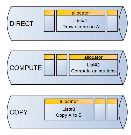
I want to emphasise one thing already: when you submit a list on the device, it is asynchronous by nature. Meaning, it can be executed right after, or it might take a while, you don't know in advance. And whereas on normal CPU-programming, you can just provide a callback or whatever mechanism that notifies the end of the task, it is less simple here.
Fence & Synchronisation
In order to be able to synchronise the work inside the GPU and also with your program, we have one main synchronisation primitive: the Fence. A fence definition is pretty simple at its core: it is a counter. It has two primitives that can be executed on queues: set a new value (called signal) or wait for a value to be reached. Moreover, the latest signal-ed fence value is also exposed to the CPU which allows your program to know if some point was reached.
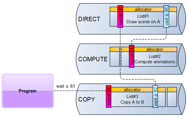
The example here shows a simple sequence where you compute animations then draw a scene, then copy to a buffer then transfer the result to your program. To do so in the right order, first, you signal the fence with some value after the animations are ready (here we use value 91), then the direct queue has to wait for this value to be reached. You can continue this pattern by signalling the next fence value (here 92) at the end of the drawing and waiting before the copy. Finally, you signal the next value (here 93) and ask your program on the CPU-side to wait for this value to be reached.
Your job as a programmer is to basically never wait for the GPU if you can help it. As they said in the Nvidia Do's and Don'ts, "Accept the fact that you are responsible for achieving and controlling GPU/CPU parallelism". If you've used previous versions of DirectX or if you played with OpenGL, you didn't need as much plumbing. But, for DirectX12 or Vulkan that is the amount of control and fine-grained details you need to dabble in.
Moreover, your job is also to limit object creations like command lists and reuse them as much as possible. However, there is one big limitation: you cannot reuse a list if it is still pending completion on the GPU. So, you will have to deal with synchronisation to make sure that you can safely reuse them.
Swap Chain
When you want to submit an image on the screen (or inside a window), it takes time to do so and it depends on your hardware. If you have a basic HD monitor, you will be able to display 1920x1080 pixels, 60 times per second. In practice, it actually means that the screen will display pixels one by one, from top-left to bottom-right and it will take ~16.6ms (=1s/60). During this time, you can not afford to display the next image that you are currently working on.
Therefore, the Swap Chain is the mechanism that will synchronise everything for you. It contains a set of N identically shaped buffers, called Back Buffers, able to hold images. At any point in time, one will be wired to the display. When ready, the swap chain can switch from one buffer to the next. Usually it happens when the display has just finished displaying one (called "V-Sync"), but you can configure it to display whenever the next image is ready, which triggers tearing artefacts.
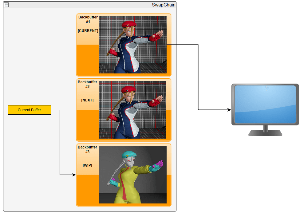
Having large values of N allows us to prepare multiple frames in advance, therefore if in case of a slowdown, we can keep giving frames to the display while we hopefully recover.
Here's the list of operations that you can do on a Swap Chain:
- Get the current available buffer.
- Mark the current buffer to be ready to be presented (called the Present operation).
It will be our job to synchronise everything and make sure that when we want to use a backbuffer, all the previous operations using it are complete. In practice, a swap-chain is attached to the window you've created using the operating system means (in my case using Win32 API).
Resource
A resource is a generic way to point to a chunk of data on the GPU. It has a description that shows its internal layout (e.g. it's a 2D 256x256 image, with 32 bits per pixel, with multiple levels of detail). It also has a state describing its usage. States are another means of synchronisation and control that the GPU can exploit to properly parallelise the work. For instance, if you want to do a copy between two resources, you need to put the source in the COPY_SOURCE state and the destination in the COPY_DEST state using a TransitionBarrier that has to be executed before the real copy command.
Finally, resources are allocated on different types of memory regions called heaps. Most notably, there are three regions: DEFAULT, UPLOAD, READBACK. Resources in DEFAULT are fully readable and writable by the GPU and have the most bandwidth, but they can't be accessed by the CPU. Resources in UPLOAD can be written by the CPU, but they offer limited bandwidth to other GPU tasks. Resources in READBACK are the other way around, they can be read by the CPU but offer limited bandwidth and very limited usage on the GPU.
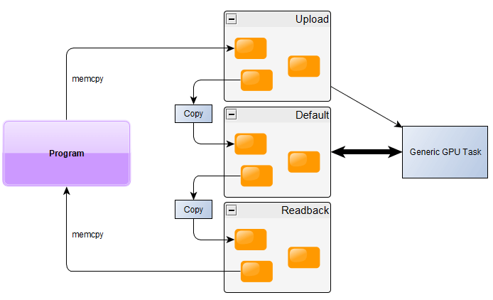
That is why, if you want to upload some data to the GPU (like a texture or a model), you need to:
- Create a temporary resource in UPLOAD
- Create a definitive resource in DEFAULT
- Copy the data using the CPU using memory copy to the address given by DirectX (this is called a Map operation).
- Copy from the temporary to definitive on the GPU
- Prepare a command list with the CopyResource and state transitions (if necessary)
- Execute it on a Copy queue.
- Signal a synchronisation fence
- Make the Direct queue wait for the fence to be reached
- Prepare a command list with the CopyResource and state transitions (if necessary)
Descriptors & Views
While a resource is a chunk of data with a structural layout description, the Descriptor is a very small piece of data that describes the usage of a piece of data. Most operations on the GPU will require descriptors for their parameters. For instance, let's say you want to fill the backbuffer with a solid colour. There is an operation for that called Clear. However, you don't give it a resource, you have to provide a RenderTargetView which is a kind of descriptor that interprets a buffer as an image used to draw things on. There are five main types of descriptors:
- CBV: Constant Buffer View. A generic data buffer used as input (e.g. light parameters).
- SRV: Shader Resource View. An image used as input (e.g. textures).
- UAV: Unordered Access View. A generic buffer or image used as input or output (usually used on compute operations).
- RTV: Render Target View. An image used as support for drawing operations.
- DSV: Depth Stencil View. An image used specifically to calculate depths during drawing.
It is also your job to manage those descriptors and allocation on the memory, because OF COURSE IT IS. So, first you have to create a Descriptor Heap which will hold a bunch of descriptors of the same type. It is always visible to the CPU and you can ask the GPU driver to keep a copy of it inside its memory to provide them to operations that require a GPU-side descriptor.
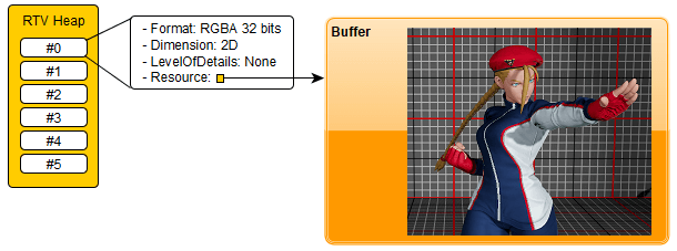
Plumbing a rendering window
Alright, let's assemble everything that we have seen and create a rendering window that will only display a solid colour:
- Create a Win32 window (not detailing this here…)
- Select the adapter that will be used, let's pick the one with the most dedicated memory
- Create the device based on the adapter
- Create a direct command queue
- Create a swap chain with 2 backbuffers using the queue and the window
- Create a fence for swap-chain synchronisation
- Create an array of 2 integers for synchronisation purposes that we will call
FenceValues - Create a descriptor heap with for render target views
- Create render target view descriptors for each backbuffer
Then, on every window update:
- Lookup the current backbuffer index =
N - If necessary, wait for the fence to reach the value
FenceValues[N] - Create or reuse a command list (not trivial, but let's say you have one list per backbuffer for now)
- Program the command list
- Transition the state of the backbuffer resource to "WRITE"
- Clear the backbuffer with a solid colour using the render target view descriptor of the backbuffer
- Transition the state of the backbuffer resource to "PRESENT"
- Transition the state of the backbuffer resource to "WRITE"
- Submit the list to the direct queue
- Present the backbuffer to the swap-chain
- Signal the fence with a new incremented value
F - Store this value for later use
FenceValues[N] = F
Congratulations… you now have a window that looks like this… weeeeee
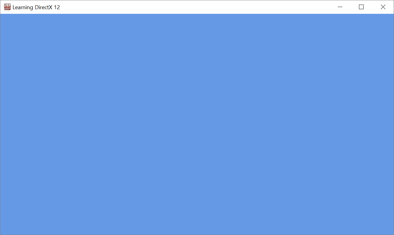
The tutorial I've mentioned earlier has a similar approach and created this program in one 750 line file. It can be compressed but not that much.
I consider this part as the foundation that you have to build upon. If you don't get those concepts well, you will struggle at some point like "why is it slow?" or "why do I need to do this to do my render?". Alright, the boring part is basically over now, we can do more interesting stuff like drawing!
Bonus point: resize the window
Let's say that we want to support resizing the window. Well… you need to resize your swap-chain buffers. And you cannot do this while any operations are running on them. So, if you want to support resize, you have to:
- Stop new operations
- Wait for GPU completion using your fence
- Call the swap-chain resize operation
- Recreate the render target views
- Notify your application that the size has changed. Most likely, other parts of the application will need to recreate a bunch of buffers as well
- Resume operations
I will not detail more but you have similar management operations that need to be done between windowed and fullscreen. Plenty of more plumbing! Let's cut this short and draw stuff on the screen now.
Let's draw
Don't get your hopes up too much yet, we still need to master a bit of plumbing. The main difference is that we have all the major concepts now, we can dedicate the time to actually think about what we need to draw on a render target. So, let's get some concepts out of the way first.
The graphics pipeline
On DirectX, when you want to draw something, you need to use a Graphics Pipeline. It is a chain of fixed operations. The whole chain takes a set of geometry data as input, a bunch of parameters, and a render target as output and it will draw on it. Interestingly, you cannot change the chain of operations but you can configure it at will: enable some parts, disable others, tweak the configuration of some stages, etc.
The structure of the graphics pipeline is documented here. But, I am going to simplify it here by keeping only the interesting operations to do the basics. Let's follow the life of a couple of triangles with colours.
Input Assembly
The input assembly is the first step. This is pretty intuitive, you have a bunch of data and you want to instruct the pipeline how to interpret it as a set of geometry elements in 3D. Additionally, on each vertex, we can provide a bunch of additional data. Here, we're going to give a colour ID. I'm not going to explain how the assembly can be configured as there are multiple ways and it's not really interesting. Do note that the order of the vertices in a triangle, called the winding, is important as it defines the orientation of the triangle (by default only the "front" face is drawn).
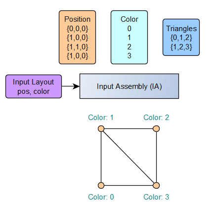
Just note that graphics cards like triangles, a lot. It's the simplest way to describe a flat surface. With four points or more you could describe a volume. Fortunately, you can compose any shape as long as you provide enough triangles. Here, in the example, we have two triangles that shape a unit square in 3D space with Z=0 with some colour ID attached to each vertex.
Vertex Shader
The vertex shader is a small program that is executed for each vertex. It transforms the data coming from the input layout and outputs a structure with some vectors (one will be the mandatory position). We are going to provide a final position and a colour data in RGB.
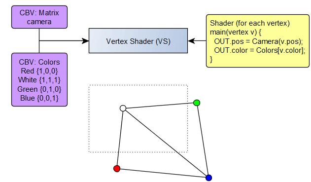
In this example, we provide two Constant Buffer Views (CBV), one is the camera matrix, and the other is the list of colour vectors. Those are provided by your program on runtime, it will be your job to either upload it to the GPU to be used, or give the GPU pointer to the buffer directly.
I'm not going to talk too much about matrices for now, the idea is that you can change your input coordinates to some coordinates relative to your viewport shown in dotted-lines (or screen if you prefer). Additionally, the new Z coordinate will indicate how far from the camera our point is.
Rasterizer
This is where for me the magic happens. The GPU will fill the triangles with all the pixels in between. If one pixel is not within the frame, it will be discarded, and additionally pixels with a Z-position below 0.0 (too close or behind us), or above 1.0 (too far away) are also discarded.
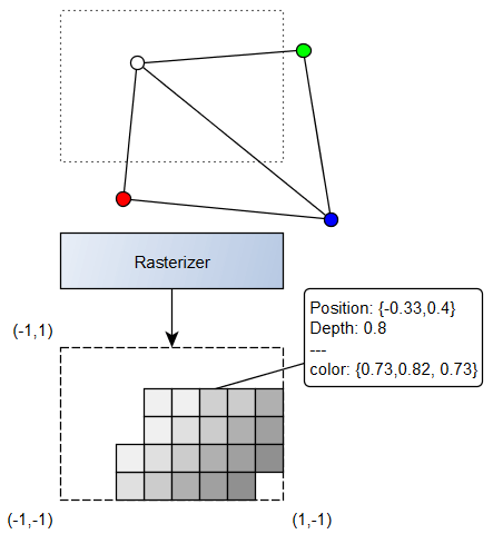
In the illustration above, you can see the rasterized frame with each pixel that passes the frame and depth selection (the depth is illustrated by the shade of grey). You can notice that the pixel on the bottom right is not drawn because it is too close to the camera.
On each pixel the data is calculated as an interpolation of the three points of the triangle. For instance with colours, if you are in the middle of the segment between a white vertex and a red vertex, you will get a light red and so on.
Pixel Shader
The pixel shader (also called fragment shader in other systems) is a mini-program executed for each visible pixel. The output is the final colour of the pixel, usually it will be in RGBA values.
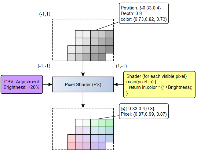
In this example, we provide some data to adjust the brightness. This is obviously a simple example and in practice you will have a lot more inputs (like textures, lights and such).
Output Merger
This is the final task. Now that we have calculated the final pixels, we need to integrate them to the final render target. Additionally, it can use what is called a Depth Buffer to test if the pixels that we want to draw are above or below the previously drawn data.
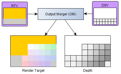
In the example, we have a render target with a previously rendered grey banner at the bottom and a yellow background. Here, we assume that all pixels are above the previous data and you can see the shape of the final render target & depth buffer which will be both updated for future calls.
Result
Using a very similar shader and pipeline, and by adding more triangles to form a cube you can draw the following rendering result.
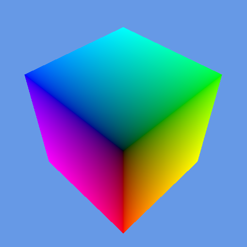
Each vertex has a different colour, each pixel in-between is drawn with a mix of the colours of each triangle (each face is actually a triangle pair). You can also note that we don't see the pixels that should be drawn in the back, they were rejected during the output merge.
Pipeline States & Signatures
Let's talk plumbing again, but don't worry it will not take that long. When you want to create a pipeline, you need to provide a configuration on how you want to shape it. Most importantly, you need to provide the shape of the input data, the (compiled) shader codes, other configuration of smaller importance and finally the list of runtime parameters.
You can think about the final pipeline as a very big function like: draw(camera, colours, brightness). Each parameter can be changed at each render if you want. This is why it is called the Root Signature, because it can literally be interpreted like a function call. This root signature will in practice be represented as a small memory block where the data for the parameters are provided. There are three ways of providing a parameter:
- As a constant. You write the data in the signature directly.
- In C language, it would be
CameraData camera
- In C language, it would be
- As a pointer to your data. This is called root descriptors which I think is confusing.
- Basically you provide a pointer to your data and declare "it's a CBV", or "it's a SRV". Because it's not a detailed descriptor its usage is limited because of the lack of metadata.
- In C language, it would be
CameraData* camera
- Basically you provide a pointer to your data and declare "it's a CBV", or "it's a SRV". Because it's not a detailed descriptor its usage is limited because of the lack of metadata.
- As a descriptor table. You can point to a descriptor heap that will provide a set of descriptors. This descriptor heap needs to be in GPU space.
- In C language, it would be something like
Descriptor textures[4]
- In C language, it would be something like
Here is a visual representation of what it can look like with the three mode usage.

Why am I talking about this: because unfortunately, you have only a maximum of 64 32bit values. So, if your camera data has 4 matrices, it fills out the space already! Understanding the limitations of each method of sending data is pretty important.
Moreover, descriptors need to be visible to the GPU and descriptors will need to be sent in a specific order while the descriptors you prepared as part of your application were created whenever the data was loaded. That is why a common pattern is to stage descriptors. You need a big heap that will be used for signatures, then allocate some spot on it whenever needed and then you can just copy the descriptor you had at load into it when you need and use this one in your signature.
The whole pipeline (i.e. the signature but also the viewport data, the render target, the depth buffer etc.) has a state called the Pipeline State Object. The command list is able to switch between different pipeline state objects, different signatures and change its state at will. Once configured, you cannot change the layout of the pipeline though.
A never ending software complexity
This goes to show you that creating a pipeline is not something that is done lightly and the more your application grows the more sub-system you require. Here's a few examples of such systems:
- Resource upload mechanism
- Temporary upload memory pool
- Descriptor staging mechanism
- State management for resources (to avoid creating barriers when it's not used)
- Command list management
This is surely a major blocker for junior engineers to start creating an engine. That is also why I consider it as one of the hardest personal projects I've worked on, and that is why the 3rd part of the tutorial linked earlier is just a bunch of heavy C++ management classes. Being a senior developer, I decided to rewrite everything myself because I didn't understand (or agree) some of the design decisions that were made. Hence, if you don't have good refactoring skills, you will never be able to try something, fail, rethink and change fast enough and it will be daunting.
Some maths
I will not dig too deep on the mathematical aspect. However, it seems important to me to talk about certain notions that you have to be fluent in to naturally manipulate drawings on this kind of system.
As you may have noted, the graphics pipeline is a very raw concept which is just a big engineering mess in the end. The only part that is inherently related to drawing is the "rasterizer" step where the GPU will fill out triangles with pixels. All the rest, and I insist, all the rest is just some maths. We are not saying to the GPU "draw a cube in 3D", we are actually computing all operations ourselves. Granted, the GPU provides all the maths tools to efficiently calculate things, but you still have to do the maths.
Fundamentals
That is why it is crucial for me that you understand linear algebra well. If necessary, you can follow 3blue1brown series on the topic or these more complete lectures from Gilbert Strang at MIT if you're discovering it or need a bit of freshening. You might have heard about quaternions for 3D, while it is technically important, it is not really necessary to understand quaternion arithmetic. The only place where you need quaternions is to create rotations, and DirectXMath provides all the necessary tools to not do the operations yourself.
However, one concept that you will often use is switching from one coordinate space to another. You will do it all the time. So, spend time polishing your notions about transformation matrices, they might come in handy..
3D Matrices
Let's say we have a bunch of vertices that represent an object in 3D, and we want to place it on our scene and point a camera at it. The first question will be: where is it in space? To place an object, there are three major operations that we can use: translate, rotate and scale. All of those can have a transformation matrix ($T$, $R$ and $S$). We can call the model matrix $M$ which composes those operations. It does the conversion between the "model space" to the "world space" uses this simple formula for each vertex $v_{model}$:
Hence, placing an object on the world, means multiplying its vertices by a matrix. Now, we need to have a matrix that is able to transform the "world space" into the "view space" (meaning the point of view of the camera). Creating such a matrix is not hard, just inverse a $TR$ matrix that would place the camera on the world. The resulting matrix is the view matrix called $V$.
Finally, we can create a matrix that transforms the space in front of us into a unit cube, the front face would be our viewport, and the depth axis will represent the distance from the camera. There are multiple ways to go about it. I will not detail them here but note there are tools to create them easily.
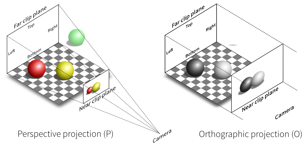
(note: I am not sure who to credit for this illustration I've seen on multiple websites…)
Let's use the perspective projection that uses 4 parameters: a field of view angle (say 90º), an aspect ratio (say 16:9), the distance between the viewpoint and the screen (say 0.1) and a point where objects are considered too far (say 100). Let's call this projection matrix $P$.
We can now create a combined matrix that will do exactly what we want. Moreover, the Z part of the vector will represent the depth scaled between 0 (near plane) and 1 (far plane).
This is magic in my eyes, you can place objects and prepare a camera in ONE vector by matrix multiplication. Obviously, these are only the fundamentals, when doing more complex stuff like shadows, or animations, you'll have to fully grasp what operations you want to do.
Let's draw something interesting
We have the fundamentals locked in. Now, we will try to draw something useful. After dabbling with some simple structures like cubes, I decided to recreate a fighting game training grid.
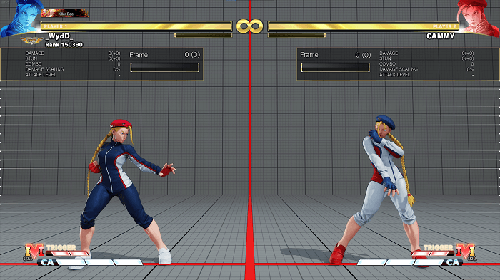
Ignoring the UI (not our focus here), we have a simple environment: just an empty room, no building, no sky, no plants. We can place any model on this for testing. And we have a simple enough light with a shadow. Bonus point: models can be animated.
Mandatory disclaimer: I will be using game resources which I have no authorisation for, and I am in no way affiliated with CAPCOM. I don't intend to even distribute this engine as is and definitely not the assets, it's just a support for education purposes.
The input data
Fortunately, I've spent years looking at the data from Street Fighter V, and extracting a model, textures and animations is not that hard using the modding tools publicly available from the modding community. Here's a screenshot of the UE Viewer that is able to preview a model and most importantly export it in a standard format.
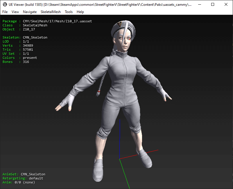
The tool supports the glTF format and I decided to go from here. After documenting myself on the topic, it's relatively straightforward. This format is basically a big JSON file alongside chunks of binary data. JSON files are easy enough to parse (I used an external library for this, no use in recreating one). And it is pretty easy to interpret even by hand, especially with the available tutorials from the glTF project directly.
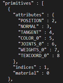
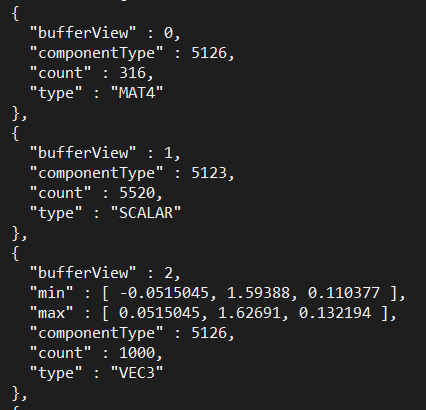
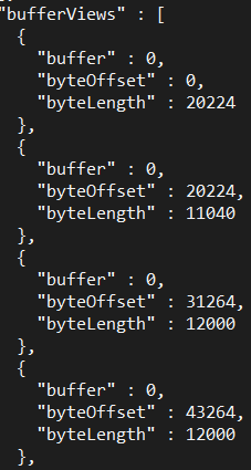
Let's look at the structure of the model: we have a bunch of primitives (e.g. the head, the hands), the indices field points to an accessor object which represents an array of 5520 scalar values that can be seen at offset 20224 of the first buffer. The indices are the list of triangles. Then, we have the attributes like the position which is an array of 1000 vectors in 3D available at offset 31264. Neat! I have my input layout ready and can send the data directly to the input assembly! We're going to see the different attributes later on.
Skip the big amount of plumbing work, and the frustration of not fully understanding everything I talked previously, I can generate this using the colour attribute in the material metadata (the colour in the vertex attribute was always white).
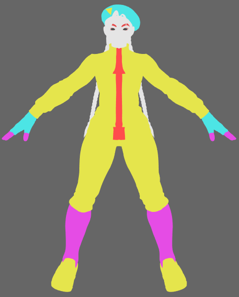
One important point to note: I'm skipping A LOT of struggles here. Especially things like the fact that glTF was made for OpenGL, which has a different coordinate system than DirectX. This messes with plenty of operations, similarly I have some materials which assume to be rendered first or with opacity etc. Just know that it's not as easy as I may make it sound here.
Add some light
Now obviously, this is crap. It is impossible to detect the embossings of the model, just the overall shape. One of the simplest tricks to do is to implement the Phong lighting model, a pretty old model from 1975 but it will get us started. The idea is really simple, there are 3 ways of being lit: ambient, diffuse and specular. Ambient is simple: we assume that the ambient light (various indirect incoming reflections from everywhere) is a constant small amount everywhere. That's basically what I've done already. Diffuse is the light that the surface scatters. Specular is the light that is reflected on the surface directly.
Diffuse
Let's ignore the specular light first. The diffuse light is simple to do: if the light comes straight at the surface normal, a lot of light will be absorbed, if it comes at an angle, it won't be as much. So, assuming that we know the surface normal $N$ and the light vector $L$ we can deduce the Diffuse formula as:
With the dot being the vector dot product, and because those vectors are unit vectors, the dot product is the cosine of the angle they form. Fortunately, we know the surface-normal! It is provided by one of the vertex attributes, we just need to multiply by the model matrix to have the normal in the world coordinates in the vertex shader, then we can apply the formula in the pixel shader directly. Moreover, the normal will be smoothed out by the rasterization process. Adding a bit of ambient, this is what we get:
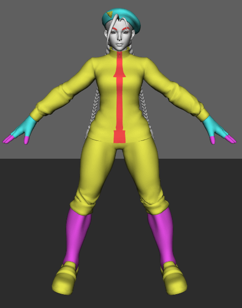
Now we are talking! We can see shapes forming. Obviously the result is very crude still but we see something.
Specular
Just for fun, let's add the specular component as well. This part of the lighting is just the part that is reflected from the surface. The theory is pretty simple, you want to amplify light when your eye points at where light is reflected.
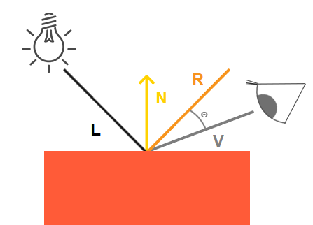
Using a simple schematic from LearnOpenGL, we can intuitively see that using the dot product of $R$ (reflection) and $V$ (view), we can have this effect. However, we need to quickly crush the result if we deviate too much from the reflection vector. The model indicates that we can use a big exponent and we obtain this neat formula:
Here's the result that we can get using a combination of each of those components of the model.
The result is very similar to above but you can see specs of lights where the normal reflects the source. Obviously in this case, the parameters are constant and it feels like a Toy's Story-like plastic puppet. But the neat thing is that this can be written in a couple of lines inside the pixel shader (which has the dot function, the vector reflect function, and all the other operations, including per-component arithmetic).
Texturing
Let's make it more interesting. Let's plonk an image on this model. Usually, that's where everything becomes really hard in tutorials. However, I've already presented all the plumbing necessary, so it's going to be faster.
From the data extraction, I could get five textures. Those are square images in 1024x1024, 2048x2048 and even 4096x4096.

Let's assume that we can read those files and get a big array of RGBA vectors (using the stbi library). Let's focus on the first one. It is the colour of the surface of the model. Obviously, a shape is complex and we have a 2D texture, but there is one attribute in the vertices called TEXCOORD (aka. "UV"). It is a 2D coordinate $(u,v)$ that points to where it's needed on those textures. The coordinates are floating-point values between 0 and 1. There might be other similar attributes but it's not the case here. Again, the rasterizer will provide the coordinate of the pixel directly, not the vertex.
Colouring
So, you know the drill now, upload the texture on GPU, create a Shader Resource View descriptor, declare a descriptor table in the signature for your textures, stage your descriptor whenever you need it, yada yada yada. The one thing that you additionally need is a sampler. A sampler provides the function sample(u,v), with $(u,v)$ being the coordinate as a floating point. Therefore, there is no notion of resolution here. The sampler is just trying to give you the best value for the point you want to reach. It can be the nearest pixel, it can be a linear approximation, it can be more complex. Fortunately, you don't have to code this, samplers are provided by DirectX as part of your pipeline configuration and become available in the pixel shader (note: you can also provide it as a parameter).
Here is the texture that will be used to get the colour of each pixel. The technical term for this is the "albedo" which corresponds to the colour lit under white light.
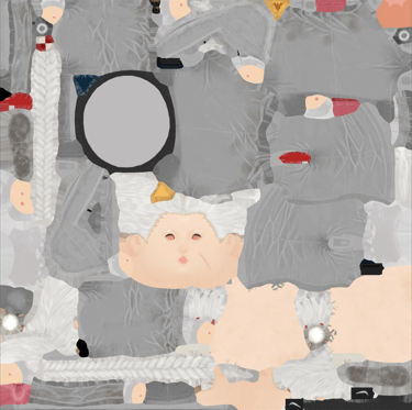
Welp, we have everything, let's recap what we have as the output of the vertex shader which will get rasterized.
{
    float4 position; // mvp * position attribute
    float3 normal;   // model * normal attribute
    float2 texCoord; // texcoord attribute
}
On the pixel shader, we just need to call the sampler on texCoord with our texture and replace our previous colour value with this new value. I've also created a quick grid texture. Here's the result we directly get which now starts to look like a real character.
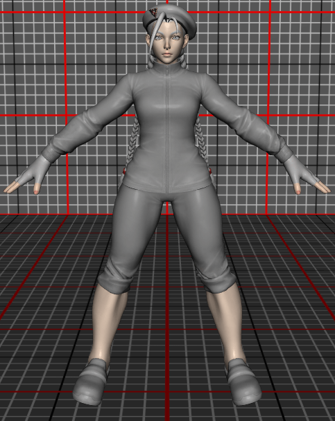
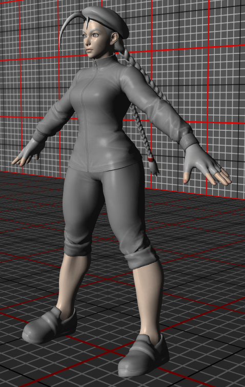
Here, I've used a sampler which provides an estimation of the pixel value using the perspective to better sample, called anisotropic sampling.
Costume colour
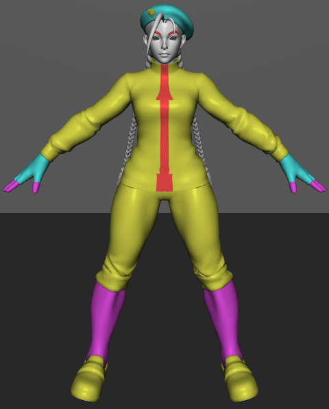
We're having something that kinda looks like the Unreal preview now. Ok, no, it's still crap. But at least the colours look normal. However, it's not what we see inside the game (see screenshot from the game earlier). The second texture called "MASK" shows a big plane composed of 4 colours: red, yellow, purple and black.
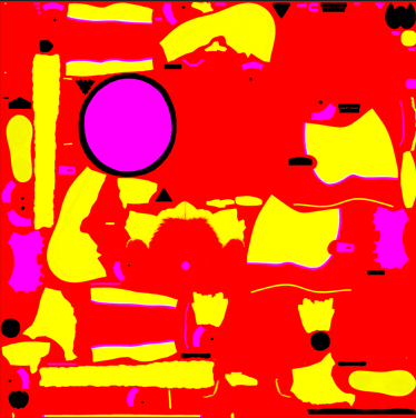
Then, when browsing the game files, I found the asset which contained the data for each costume colour. By tweaking my data extraction, I was able to find a set of RGBA values for costumes. I now have:
(CostumeID, MaterialID, MaskID) ⇒ RGBA
The MaskID value can have the value 0, 1 or 2. If the mask colour from the texture is black: just use the original colour, otherwise: red = 0, yellow = 1, purple (or else) = 2. Obviously, we will not paint the different materials with a solid colour, we still need to keep the original shading. After trying a couple of approaches, it seems that what Street Fighter V used the geometric mean $\sqrt{\textrm{texture}*\textrm{mask}}$.
In practice, it's like before, just use the second texture as another argument and sample it to determine the type of mask applied. Then, just calculate the new value using the previous formula. Here's what we get for the two costume colours presented in the game screenshot.
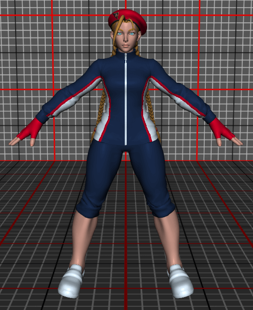
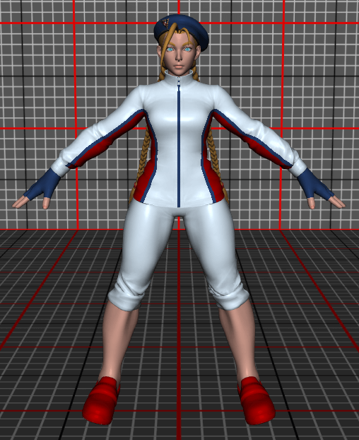
Skeleton & Animation
Alright, it's starting to be boring to look at the same T-pose every time. We can try to load the animation data from the glTF as well but it needs a bit of background to understand how it works. Before starting this project, I only knew that meshes had some kind of skeleton which gets animated. Which is not false, but not really complete.
So, here's the idea. Everything starts with the structure of a skeleton is pretty simple: it's a tree basically. You have a bunch of nodes, each node has one parent or is a root node.
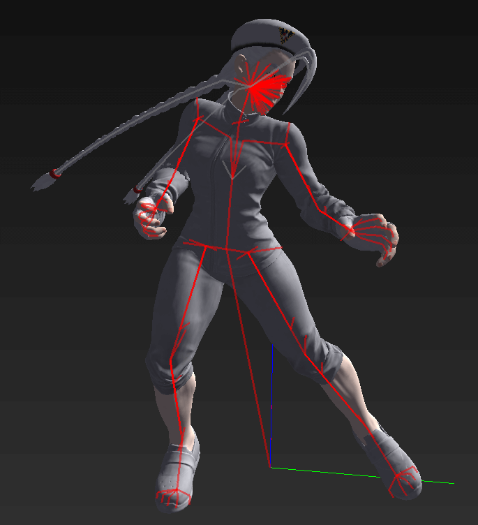
For each node, to go from the parent to it, you have a local transformation matrix composed of a translation and a rotation (starting from the parent position). Then, from this new node, you add another transformation matrix to go to another node and so on. Here's one simple path for example: base > pelvis > right leg top > knee > ankle > foot > toes.
What is interesting is that this structure can easily be animated. Each translation and rotation matrix can be changed at will! Moreover, if you change one component, say the rotation of the knee, all the children nodes will follow the rotation as well by definition (because you only define local transformations). The only question that remains is this: is it possible to provide a transformation between the resting position and the new position. As a matter of fact it's pretty simple.
Let's say the local transforms for the n-th node to the root are $T_n(t)$ and $R_n(t)$ at time $t$. And the resting positions transforms are $T_n^0$ and $R_n^0$. Then, the global transform of this node is $P^0=T^0_nR^0_n$...$T_0^0R_0^0$ for resting and $P(t)=T_n(t)R_n(t)...T_0(t)R_0(t)$. Therefore, the transform between resting and the new position is $P(t).P_0^{-1}$.
Fortunately, most of these operations can be grouped by parent, and the computation is not that intensive. The main point is that, it is possible to compute for each node a way to get from the resting point to the new position.
Now, how does that apply to the mesh? On the vertex attributes, two were dedicated to that, "JOINTS" and "WEIGHTS". The idea is very simple and can be summed up in two vertex shader instructions.
weights[0] * transform[joints[0]] +
weights[1] * transform[joints[1]] +
weights[2] * transform[joints[2]] +
weights[3] * transform[joints[3]]
);
position = mul(skin, position);
Weights and joints provide a linear combination of up to four nodes for each vertex (the attributes are 4D vectors). Therefore, by just combining all the transform matrices, each vertex will follow the skeleton because they follow the transformations that the bones do.
In terms of plumbing,the difference is that we need to compute the matrices for each node and such which is not really a small feat. For instance, animations are defined as a timeline when at $t=1$ we are somewhere and $t=3$ for instance we have moved. But, we need to implement time interpolation to smooth the transition from one to the next. Also, we need to properly keep track of all the transformation matrices that need to be computed. And finally, we can send those matrices to the vertex shader where the position of each vertex will change based on this. Now, we can draw a combat position:
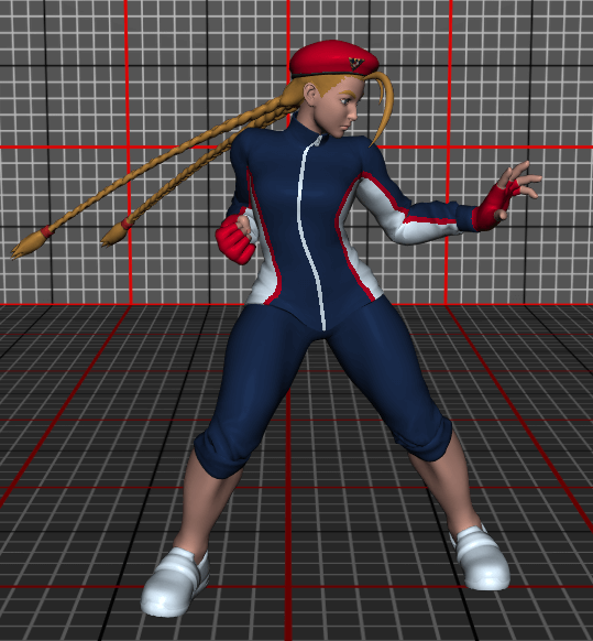
Note: as you can see the braids are not animated. This is normal and is part of the rest of the engine which handles dedicated routines for clothes and hairs for instance. I will gladly ignore this here. It might be a project for later.
Adding a simple UI
We're starting to have too many features in this project. We need some kind of UI in order to control the different knobs and test things out. For this, a very simple way of doing it is the über-awesome project called "Dear ImGui". This is just the PERFECT tool to do experiments for this kind of project. It is very simple to create a window with settings, it integrates with every graphics APIs, it doesn't require other dependencies, it just works.
As a first implementation, I just added:
- A selector to pick the costume colour
- A slider to rotate the model easily
- A selector to pick the animation
- A slider to select the animation time
- A play button that will automatically play the animation (It just increments the time on each frame)
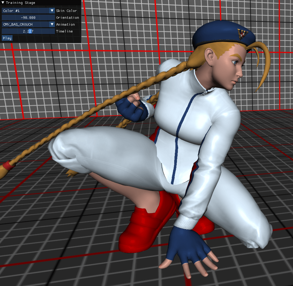
We finally; FINALLY; have the framework I talked about at the beginning of this article: a playground to be creative and test things out.
Making the scene pretty
We have a decent scene where things are drawn, fair enough. However, it would be lying to call this pretty, at least not in 2022. The goal of this section is to make this scene just pretty, by a standard level of decent.
Fixing artefacts: antialiasing and mipmapping
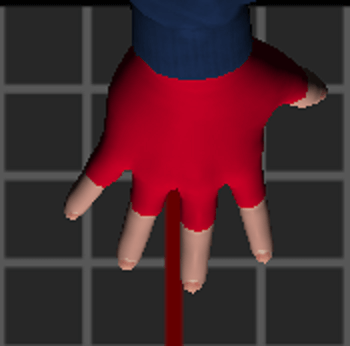
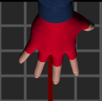
The first very standard improvement that can be implemented is to fix the ragged edges due to the rasterizing process. This rendering artefact is called "aliasing" and you have surely heard of it. One idea, called Multisample Anti-aliasing or MSAA, is that rather than calling the rasterizer once with a fixed grid, we can call it multiple times with a very subtle shift. Each result will be stored in a separate buffer, then we can average each pixel and have a smoother render. There are other approaches but for now it will be fine.
To implement this, you need to declare the rendering target with a "sample" level above 1. This will create the necessary buffers to hold all the samples. Obviously, the buffer will be way bigger, for instance if you have a sample level of 8, it will take 8x amount of memory. You don't need anything more to perform the render, it will be handled by the graphics pipeline. However, we need to convert a multisampled render target to a normal one (e.g. a backbuffer). Fortunately, the operation called "Resolve" does this for you. Here is the magnified result:
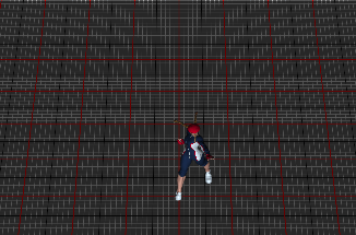
Then, we need to fix the weird shapes on textures that appear with long distances, called Moiré patterns. This is due to the way sampling works, on one pixel, we try to cram potentially plenty of texture pixels (called texels). When the pixel size is similar to the texel size, then it's normal to have a continuity between nearby pixels. But when the pixel is way bigger than the texel, then your nearby pixels cannot ensure smoothness. Even using advanced anisotropic sampling, we still see patterns like this when displaying a grid.
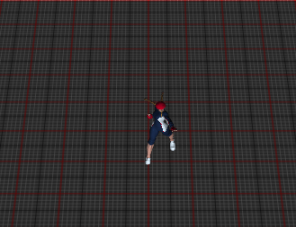
To solve this issue, the common technique is to use mipmapping. The idea is to generate zoomed out versions of the texture, down to 1x1 pixel. Then, you can ask the sampler to use the level of detail where the texel size is close to your pixel size, solving the problem of continuity. Once properly configured, the same scene will look like this.
However, generating the different levels of details is not automatic and there is no helper method or pre-configured pipeline to do so. Yay, new plumbing to do. I will NOT detail this here because I barely scraped the concept myself. I presented the "graphics pipeline" before. There is another type of pipeline called the "Compute Pipeline". It is way simpler and it has only one step. It allows you to just run one function, the compute shader, but in parallel on the GPU. Here, we just design a task that takes care of computing one level of detail (you divide the width/height by two, and yes you have to deal with the remainder if needed), then run it as many times as needed. The compute shader, like all shaders, is able to have access to textures using SRVs, to allow texture sampling; but also UAVs, to allow writing the result in the buffer.
Normal mapping
Now, we're starting to enter into less software engineering intensive and more mathematically intensive ideas. As you have seen, the surface of the mesh is very flat, very pure, hence this "plastic" rendering that just came out of the mould. However, inside the game, we know that the surface is not as pure. This is where the third texture from our set comes into place: the normal texture.
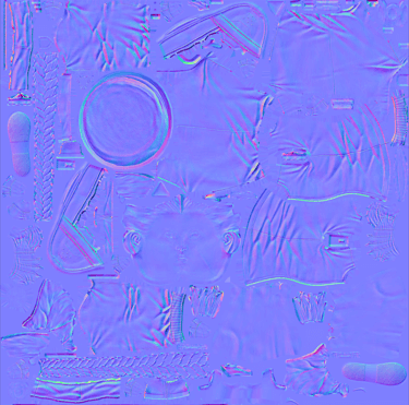
The intuition behind this process is simple in theory but is hard to wrap your head around in practice. The texture describes how the surface normal is slightly shifted compared to the one provided by the vertices. For instance, the fibres on a cloth make the light bounce in various ways, however from the mesh point of view, the surface shape is the same and it would be stupidly complex to model each yarn individually. The normal texture allows us to cheat by giving relief or depth to a flat surface by just reflecting light in a different direction. This allows artists to provide a great amount of details. Here is the normal texture for the sole of the shoes for example.
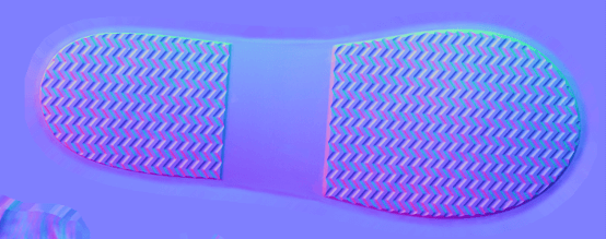
What do we read on this texture? This is a RGB texture, and assuming that we have a value $n=(r,g,b)$, that we easily translate to normalised $[0,1]$ coordinates. The normal vector for this point will be $N=(n-0.5)*2$ to have values ranging in $[-1,1]$. This vector expresses where the local normal is on a flat surface on the $XY$ plane. That is why the dominant colour is purple, because the colour value $(0.5, 0.5, 1)$ translates to the Z-vector $(0, 0, 1)$. Unfortunately, we do not know the orientation of the $XY$ plane on the mesh. We need to formalise this a bit better.
For each vertex, we define a new coordinate space: the Tangent Space. This space is the world space rotated in a way where the vertex normal is facing positive $Z$, the vertex tangent is facing positive $X$ and the bi-tangent is facing positive $Y$. Where does tangent and bi-tangent come from? The tangent is provided as a vertex attribute. The bi-tangent can be computed quickly: because it needs to be orthogonal it will be $N\times T$ or $T\times N$. The 4th dimension of the tangent attribute allows us to decide one of the other (also found in Unity).
Our goal now is to create the transformation matrix to go from world space to tangent space for the current vertex. We assume to have $M$ the model transformation matrix, and $A$ the transform matrix for the animation of the current vertex. Therefore, the total transformation of the vertex coordinates is $MA.v$. In our case, the tangent space only cares about rotation. We can use here a quick hack: the top left $3\times 3$ section of the transformation matrix is the rotation and scale. Let's note the operation that extract the normalised rotated vector after $MA$:
We can now compute in world space the normal $N=T_{MS\rightarrow WS}(n)$, tangent $T=T_{MS\rightarrow WS}(t_{xyz})$ and $B=N\times t_w T$. If you remember your textbook linear algebra, if you have orthogonal normal vectors, then the matrix with one vector per column will provide a transform matrix from this space to world space. If it's not intuitive for you, you can convince yourself by multiplying $[T,B,N]$ by the tangent-space normal vector $(0,0,1)$, you will get the world-space vector $N$. Here we want the inverse operation, but fortunately for orthogonal matrices, we can just take the transposed matrix.
We can just multiply each vector in world space that is necessary for lighting by this matrix. Therefore we need to apply the coordinate change to: the vertex position, the view position, and the light position (or orientation). Then we can send them to the pixel shader.
On the pixel shader, we replace the normal by the data read on the texture at the given coordinate. The rest of the operations, like computing the view direction, is already done on tangent space, so nothing additional is needed. Here is the final result on some selected parts:
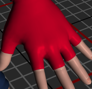
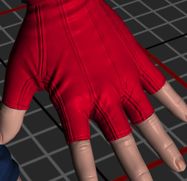


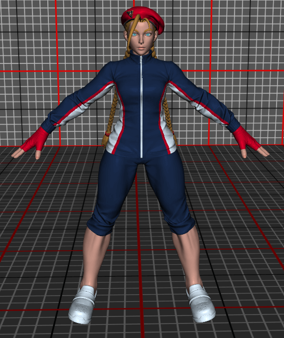
And here is the overview of the total model. Now, it's starting to look like a model that has a decent shape.
Light sources & Tone mapping
Currently we have dealt with only one light source coming from the Z direction. What if we add other light sources? Do we just add the results of the lighting model for each source? Will it go above our $[0, 1]$ range? Unfortunately, we cannot answer those questions without stepping into a world of chaos because we have to deal with light intensities and colour perception. If you're not aware, this is a very hard topic even though it's not that hard to implement. If you're a photographer, I'm pretty sure you know those.
Let's state the two facts that make our life horrible (as programmers or artists at least):
- There is no upper limit to the amount of light energy that a source can emit
- meaning: if you look at the sun, it's not just the colour #FFFFFF
- meaning: if you look at the sun, it's not just the colour #FFFFFF
- Light perception by the eye is not linear
- meaning: #808080 on your screen is not half the amount of light than #FFFFFF
- meaning: #808080 on your screen is not half the amount of light than #FFFFFF
The first conclusion is that we can not encode light data as a float between 0 and 1. It's actually between $0$ and $+\infty$. This is what HDR screens kinda do: they grant a larger range than just $[0, 1]$ to allow for bigger changes of light intensity. The second conclusion is that our lighting must be made in a separate space in order to do linear operations on it. I'm not going to dive too much into the possible options and the artistic or scientific qualities of each. I'm just going to give you the intuition that will allow us to do operations.
Here's how the operations look for a simple colour lit by three light sources.
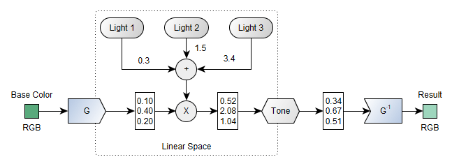
We transform the colour data using a function $G$ to a new vector with float coordinates. We are now allowed to do a bunch of linear operations, here let's just multiply this vector by the sum of the light for each source. As a result, we have a vector describing how much light it receives for each primary colour. We can call another function called Tone whose job is to transform this unbounded vector to $[0, 1]$. And finally, we can call $G^{-1}$ to go back to something that we can show to the user.
The $G$ function is called the gamma decoding (or expansion) and its inverse is the gamma encoding (or compression). It comes from one simple version where $G: x\mapsto x^{1/\gamma}$ with $\gamma$ being a constant (often 2.2). And the tone mapping function can be very simple like the simple "Reinhard" function $\textrm{Tone}: x \mapsto \frac{x}{x+1}$.
Because I like being fancy, I'm using the sRGB standard transformation functions and I will use the Uncharted 2 tone mapping which are commonly used in the gaming industry. I could have picked other things or have configured it differently, but this needs an expert and artistic point of view that I don't have.
After adding three points of lights and fiddling with their position a bit, here's the render I'm getting now:
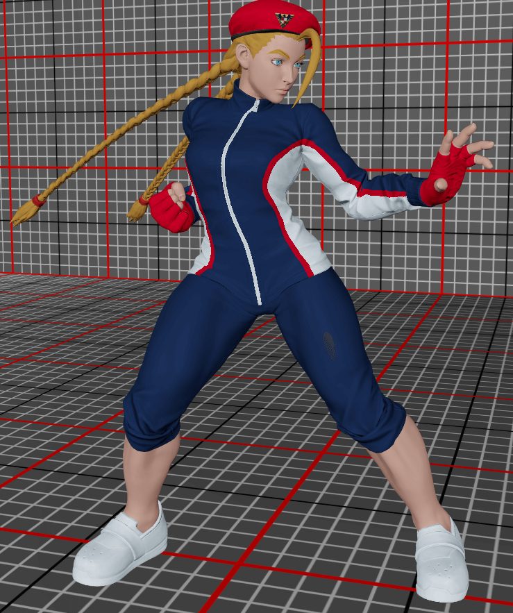
As you can see, the gradients are smoother now and feel more natural than the previous render we had. You could play with this A LOT MORE. And I'm pretty sure my lighting configuration is crap now. But I don't want to spend my time here because the lighting model is going to completely change in the next section.
Physically Based Rendering (PBR)
The point of PBR is to be able to define a set of parameters to best describe a material behaviour with the light. We touched it a bit when we tuned the amount of diffuse and specular light, but this goes beyond it. I will only present two main concepts.
The first idea is how to think about the incoming light. As presented before, the light is partly reflected and the rest is absorbed, bounces on some particles and might be scattered basically everywhere.
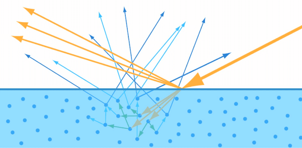
PBR tries to model how much energy is diffused and how much specular reflection you have for each angle. To better understand how deep the rabbit hole goes, let me describe microfacet theory. The idea is that surfaces are never mirror-polished. What you can assume is that a surface is composed of microfacets oriented at different angles scattering light.
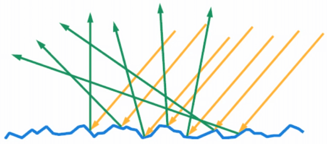
How those microfacets work is defined by the "BRDF" (Bidirectional Reflectance Distribution Function). This function is pretty complex but you have 3 main parts:
- F: the Fresnel reflectance; how much light can be reflected?
- D: the distribution function; what is the ratio of facets pointing to the viewing direction?
- G: the geometry function; how likely a facet might be blocked by other facets?
Combining all this knowledge using functions and parameters modelled from real materials and you will get the lighting model that tries to mimic reality. Hopefully by now, you've got a taste of how deep this topic can go. I'm now assuming that we have a working formula and I'm just going to spend time showing the parameters that Street Fighter V (and inherently Unreal 4, inspired by Disney's model but simplified) is using to model lighting. In order to test this, I added a material tester that applies light to a sphere. Plumbing-wise, not much new to tell, I create a dedicated render target with the flag to tell that I want to use it as a shader resource later. I rendered a sphere on it using the same pipeline with a fixed light and material properties. Then, I staged the render target as a shader resource for the GUI and displayed it.
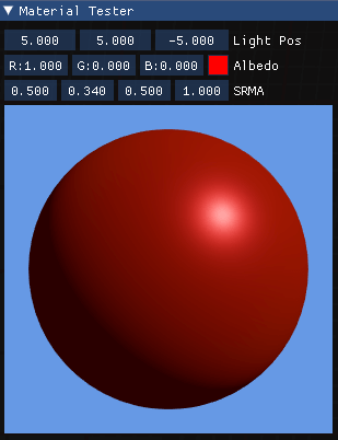
Now, let's dig into the four parameters mysteriously called "SRMA" in the GUI. Starting from here, my objective is to try to find the same kind of render that I see in the game. My interpretation will be wrong, my lighting model will be wrong. I'm barely understanding half of what's going on here, but I'm trying my best.
Specular
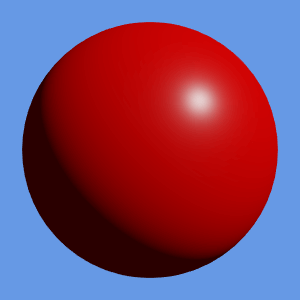
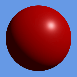
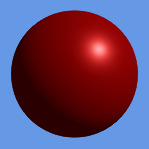
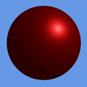
The specular component describes how much the light is reflected.
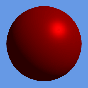
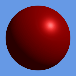
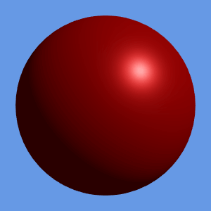
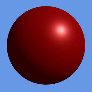
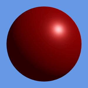
This parameter is described in Disney's model but was abandoned in Unreal 4 because it gets confused with metallic. I mean, I'm still confused by it. Disney's model also has a "tint" parameter. So, basically I used the formula from the specular component (which influences Fresnel F0 parameter). No idea how accurate it is but we'll go with it.
Roughness
This is the king of the PBR parameters for me. This describes how rough a surface is. Basically, it influences how scattered the specular light is.
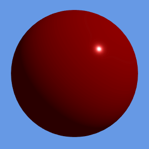
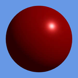



Metallic
The metallic parameter tells if the material is a metal (only reflect) or a dielectric (only absorbs). This will have a big impact on the diffuse layer.
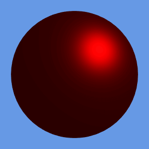
Ambient occlusion
This is a simple one. It just describes how much ambient light can be shown. This is important locally as some material might have zones where light has a hard time reaching, therefore it should just be black.
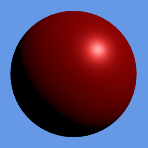
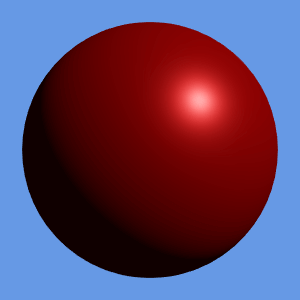
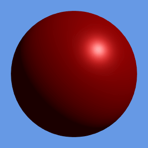
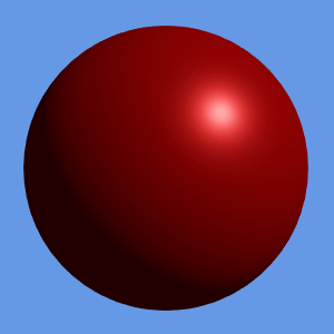
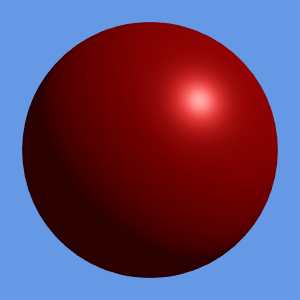
Assembling everything
In order to use those parameters, we can use the data available as part of the SRMA texture.
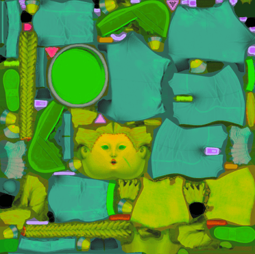
It gives a value for the four components that we need. As always, we can add it as a parameter to our shader and plug our values to our light model and we get this.
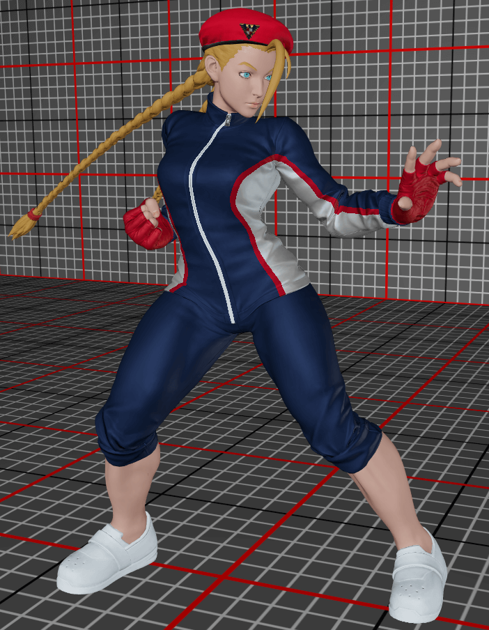
I have a couple of observations here:
- The sides should be white but the metallic parameter makes them grey-ish
- The skin feels too grey and doesn't have the distinctive "pink" colour
- The cloth specular looks great
- The skin roughness seems correct
Here, I'm going to assume one thing: we're in a cartoon-world and the energy conservation doesn't stand. While PBR ensures conservation of energy (of course it does), I'm going to change the model by saturating the diffuse component as before and not introduce the metallic parameter in this phase. This will beam diffuse on top of the specular component. However, when looking at the badge on the hat, I think we're going well. I tried to use Disney's model for diffuse which is more complex, it looks a bit closer to the result but still not quite, so in the meantime, I'm going for it.


This looks more like what you see in the game and here's what it looks like for the whole model. We're now reaching a pleasing result. But the skin is still off.
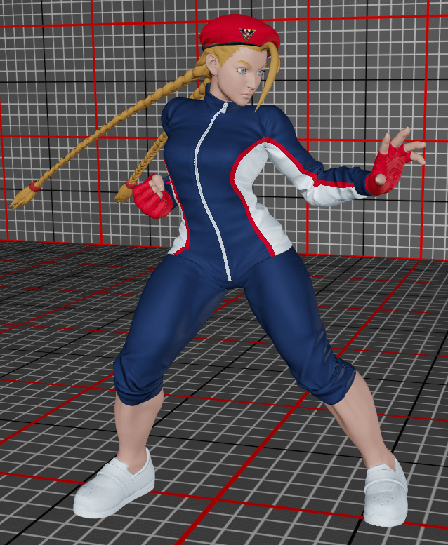
Subsurface scattering (kinda, but not really)
So, this is a big topic that I will skip gladly. The subsurface scattering basically defines that when you have a semi-translucent material, the light will glow through the surface. This is pretty important to make a skin look "alive" (94% of the light is subsurface scattering on skin apparently).
In order to do real subsurface scattering, you need a whole lot of computing because you need to compute transparency and stuff. We're not going to do that, I'm going to steal the same subsurface approximation that the old Disney model does in order to have an added tint basically. I blindly copy-pasted the implementation, and did the same trick as before (I'm not mixing the diffuse, I'm adding more light on top).
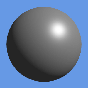
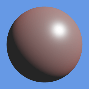
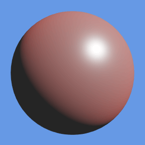
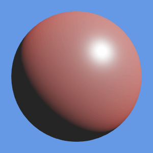
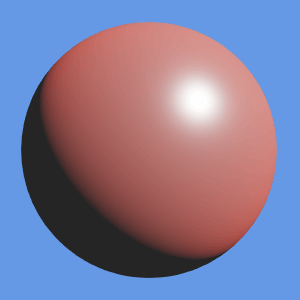
The data for subsurface scattering comes from the SSS texture.
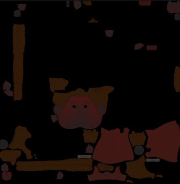
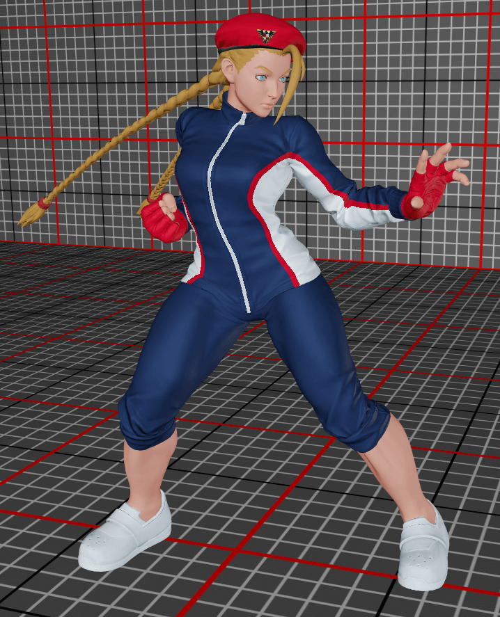
The first three components will provide the colour and the final component on the alpha channel of the texture will give us the strength of the subsurface scattering. And here's the final result of our new lighting model and considering that I'm discovering this as we go, it will be fine.
Shadows
And for the finale: let's add a bunch of shades in the scene. This will make the render look natural. If you look at the previous render, you can see that something is wrong because everything is lit everywhere. However, creating a shadow is one of the more intensive operations computationally speaking.
Here's the gist of it: let's draw the scene from the perspective of the light. Let's say that we also want to do a cone of light like a real spotlight. Here is what it would look like for its point of view using the same pipeline that we've used.
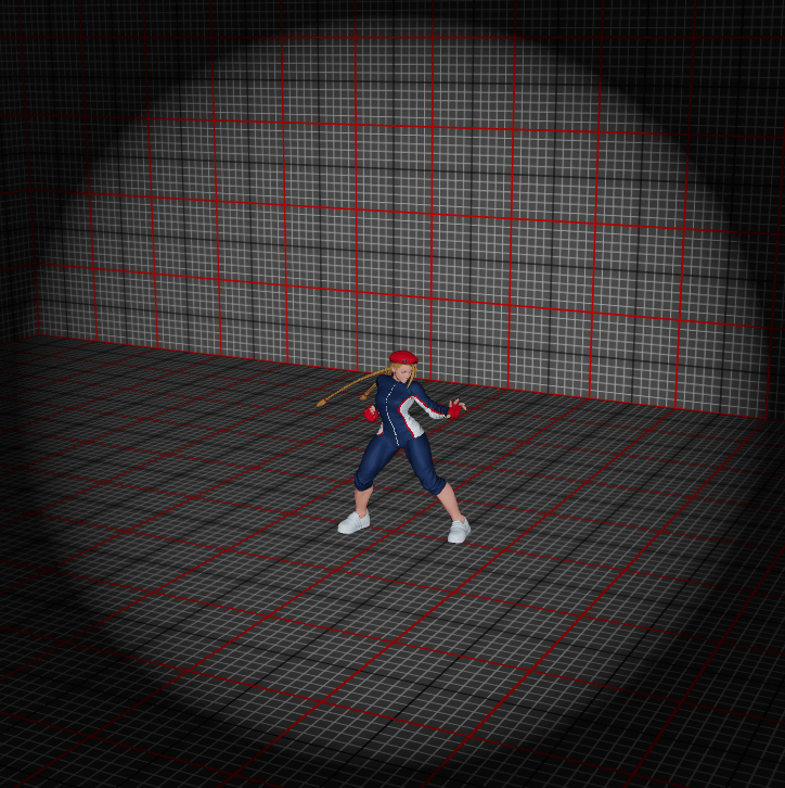
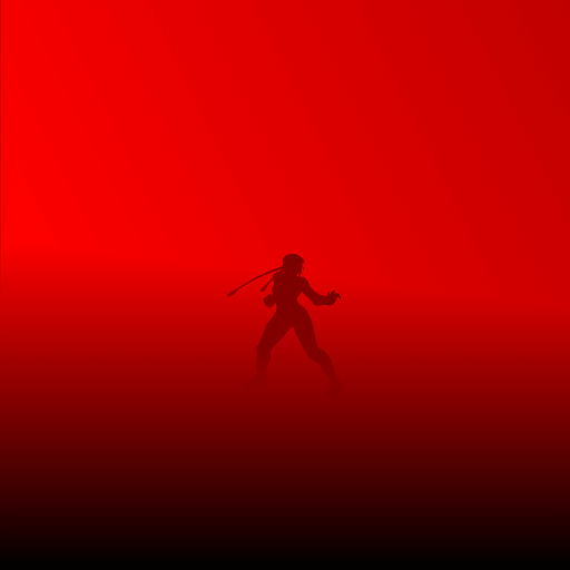
The render image is actually NOT useful, we don't care about how pixels are from the point of view of a light. However, we are VERY interested in the depth buffer. By definition, for each pixel on its screen, the depth buffer will keep a value of the closest mesh that it can see. Thus, all points that are further away than this depth value are blocked by it. This is the core intuition behind "Shadow Mapping", we keep a depth map for each shadow-generating source of light.
Therefore, we need to render the scene for each light source. However, this is a bit less heavy as we:
- Don't care about the pixel shader
- Don't care about the lighting model (duh!)
- Don't care about computing normals
- Don't care about tangent space
- Don't care about computing normals
We can create a new pipeline with a very simple vertex shader, no pixel shader (it will only do the depth blending) and only two parameters: the matrix that calculates the projection from the point of view of the light and the pack of transform matrices for the skeleton animation. We can assume that we now have all shadow maps computed.
The intuition is the following: for any point in the world, if we see it from the point of view of the light, we get a new $(x, y, z)$ point. By comparing the $z$ coordinate with the value depthmap(x,y) we can determine if our point is behind another object.
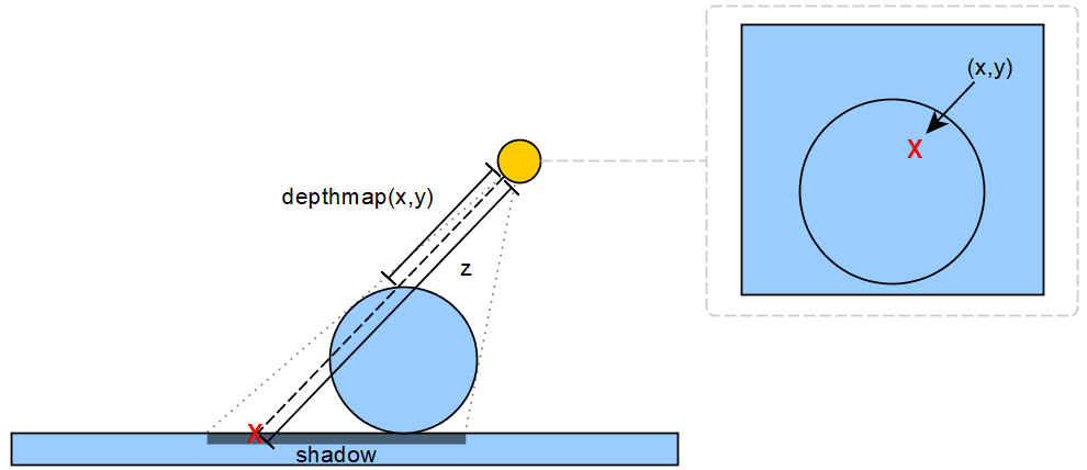
How do we use this new data to draw shadows in our main scene rendering now? There are different ways about it, but here's how I did it:
- I'm sending the projection matrices for each light to the vertex shader
- On the vertex shader, for each light source
- Using the vertex world-space position, I compute the projected position of the current vertex with regards to the point of view of the light.
- Using the vertex world-space position, I compute the projected position of the current vertex with regards to the point of view of the light.
- I'm sending each depth buffer as a shader resource view for the pixel shader
- On the pixel shader, for each light source
- I gather the coordinates from the light's perspective and the depth for the current pixel
- I will skip calculate lighting if:
- The current depth is outside $[0, 1]$
- The coordinates are not inside a circle of size $1$ (this generates the spotlight shape)
- The local depth is below the value sampled from the depth map
- The current depth is outside $[0, 1]$
- Then I apply a light attenuation: $\frac{1-\textrm{radius}^2}{1+k*\textrm{distance}^2}$. ($\textrm{radius}$ = distance to the centre of the shadow map, $\textrm{distance}$ = the distance between the light source and the target).
- I gather the coordinates from the light's perspective and the depth for the current pixel
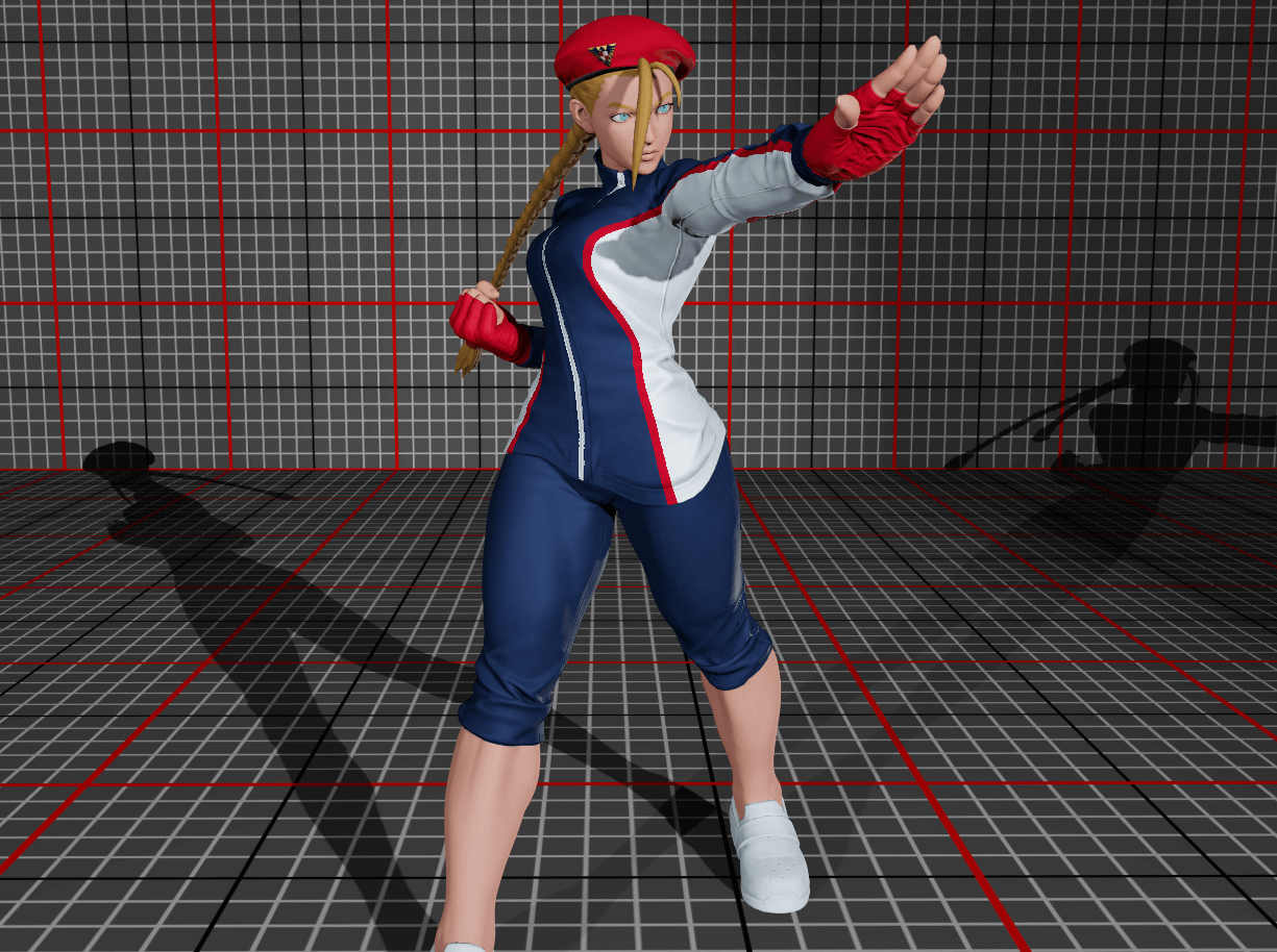
Here is the result that we get after applying everything I mentioned (which is a lot, I know).
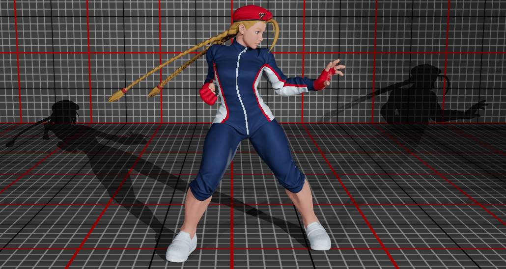
The shadow maps were created using big 4096x4096 buffers. However, when you look at it closely, you can already see some ragged edges on the shadows (see below). This is to be expected because, we are reading the data from a map which has a limited resolution and the decision about "do I light it or not" is binary. One easy fix for this is to just sample other nearby points on the shadow map to detect the change. Here, I'm going to sample 16 times around the target using texel sizes.
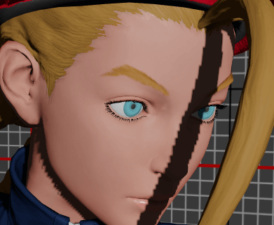
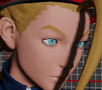
And that's it for shadows! I purposely skipped some details about shadow maps like shadow acne and peter panning which make your shadow weird in practice. If you are interested in this topic, Microsoft has a good page for improving the quality of your shadow maps. We finally get this result:
To discover the final and the engine in action, check out this video showing the engine in action with the UI.
Conclusion & Follow-Ups
To properly conclude this personal project, let's summarise the main takeaways:
Creating a 3D engine is hard. Like real hard. I still think that this is a great challenge though. It took me about 2 months of personal free time and as we discussed my starting knowledge was only bits and pieces I got here and there. However, I believe I am a senior developer who's seen a lot of different concepts and I'm able to learn fast, so it might take you more time, or less depending on how much you want to put in.
GPUs have their own special language and ways which are completely different to what we find in the CPU-space. Interestingly, the general trend over the years is to have more and more control on the operations. If we are thinking about asynchronous programming like what you can see in the big-data / AI space: they always try to hide the complexity to the programmer. Interestingly it's not the case here, quite the opposite. All modern graphics APIs (Metal, DirectX12 or Vulkan) are all low-level interfaces where you have to deal with things yourself and in detail.
There is no magic, only maths. This is what struck me the most. There is no primitive like "do lights" or "do shadows", you have to compute this yourself by laying out equations sometimes. I truly believe that even non-maths people might find this enjoyable because when you just state the question like "I want it to be brighter", you need to think about how you would solve this, try things out and eventually succeed.
Don't create your engine if you want to focus on artistic creation. Creating an engine is a feat but I see it as an engineering craft. While it may be aesthetic for my eyes, I've spent 95% of my time on the creation of the engine and maybe 5% on "how can it be more beautiful". If you want to create a game, or a beautiful scene, or explore graphical ideas like what Sebastian Lague does, do it in an engine. We live in a world where you have a lot of engines out there that you can try out for free and just create. Even big mammoths like Unreal or Unity which are heavily used in best-seller games (and even cinema) are available for free.
Finally, I wanted to talk about what I am missing in my little project and what I would like to add if I put my mind to it. I have accumulated too much knowledge to keep it for myself so I had to write this first, but afterwards, who knows?
Adding physics: hair, cloths & gravity
That is the very first thing I would like to explore. Currently all the nodes of my skeleton obey the strict law of the animation system which is derived from data. However, as we have seen, the braids are rigid as sticks, because in Street Fighter they are driven by gravity, momentum and collisions, in other words: physics simulation. Adding this can be simple like: I spawn the character above the ground and she falls until she reaches the ground.
But for braids, we need to blend the simulation with the character animation and not have the hair blindly move inside the body, so we need collisions and so on. And the pinnacle of this challenge will be met with clothes. On this model, we have no floating parts but other ones have capes, robes and hair bands. This will be another challenge.
Deferred rendering pipeline
I couldn't talk about rendering without mentioning deferred rendering. In my engine, I've rendered the scene in one big pass of one graphical pipeline (aside shadows). However, a very common approach is to split the rendering in plenty of passes. For instance, with one pixel shader pass, you could render at the same time an image that has normals, and an image that has the albedo, then do a new pipeline to calculate lighting. This is a way to split the work and assemble more complex scenes. If you want to see how a scene is composed using this technique, I highly recommend reading this blog post from Adrian Courrèges who reverse-engineered the rendering of one frame of GTA V, a true gem.
Reflections, Fog & Stuff
There are plenty of things to do on a 3D engine, and because as I stated, everything is maths, it will require no small amount of tricks. For instance, currently, I am not sure how to render a mirror in the world. I know that it will require rendering my scene twice, but are there other ideas?
Same thing for fog generation, you could just do it as a rendering of semi-transparent texture over a render target, however, in order for it to be realistic, what does it entail?
If I want to render real metals which are very shiny and will reflect all parts of the scene, how will it be implemented? I know that the general idea is to render the six faces of a box that represents the full view of the sky / ground but how hard is it to do lighting with it? What about other sources of light? How hard will it be to generate a good shadow map?
And so on, and so on.
Game engine
I mean, why stop there? I could do a whole game engine. What's the difference between what I've done and a game engine? Well, rendering is one subsystem, a real game engine is way bigger than that. Here I manually added Cammy on the scene and looked at the render. In a game engine, she would be one of the entities in the list of all things loaded. And those entities are modified by the inputs of the player and other routines that you have crafted. Basically my stuff is the small sandbox, a game engine is the real product.
Just chill… please
Seriously. I just need to let it go. One thing is for sure, it has sparked a bunch of creativity that was stuck in me for a couple of months. It was way too long but I had to write all those things that were rambling in my mind for a while now. I hope that it was educational and I will see you around.
Finally, I would like to give my thanks to Ragnarork and panthavma who were kind enough to proof-read early versions of this article and provided detailed feedback!
Source & Useful links
The final source code is available on my gitlab if you are curious. Just note that it was never going to be a tutorial, but if you want to look at it, it's there.
- Learning DirectX 12 - Jeremiah at 3DGEP
- Very useful tool to better understand the syntax and constraints behind DirectX12
- Very useful tool to better understand the syntax and constraints behind DirectX12
- Learn OpenGL - Joey de Vries
- Even though it's for OpenGL, it details the theory of all the standard rendering techniques and it's invaluable
- Even though it's for OpenGL, it details the theory of all the standard rendering techniques and it's invaluable
- Direct3D 12 programming guide - Microsoft
- Ok it's cliché, but it is actually very useful, there are a lot of details about every piece of DirectX.
- Ok it's cliché, but it is actually very useful, there are a lot of details about every piece of DirectX.
- GTA V - Graphics Study - Adrian Courrèges
- Very inspiring to see how it works in real games. His whole blog is really interesting.
- Very inspiring to see how it works in real games. His whole blog is really interesting.
- SIGGRAPH 2012 Course: Practical Physically Based Shading in Film and Game Production - Stephen Hill et al.
- My first dive into "real rendering" with researchers and engineers talking about shading. This resource is impressive, it has slides but also full course notes and even mathematica notebooks.
- I highly suggest this video form of the first talk (the 2016 version): Physics and Math of Shading - Naty Hoffman
- My first dive into "real rendering" with researchers and engineers talking about shading. This resource is impressive, it has slides but also full course notes and even mathematica notebooks.
- Tone Mapping - Matt Taylor (64)
- Goes deep into what tone mapping is and what kinds there are.
- Goes deep into what tone mapping is and what kinds there are.
- DX12 Do's and Don'ts - NVIDIA
- Great resource to understand what are the good practices to follow
- Great resource to understand what are the good practices to follow
- glTF Tutorials - Khronos Group
- Absolutely necessary to understand how to read glTF data.
- Absolutely necessary to understand how to read glTF data.
